
The Bass++ Drum Voice Project
A Dynamic Drum Voice Module
At this writing (August of 2008) the Bass++ is the latest of a triumverate of percussive voices designed by Thomas Henry since the halcyion days of Midwest Analog.
The name "Bass++" is derived from the fact that this module can deliver a supremely fine bass voice. The "++" indicates that it is not "just" a bass drum voice. As is customary in all of Thomas' percussive voice modules, a considerable degree of control is included so that one is not locked into a particular drum sound. This handy module can produce not only bass drum voices, but also produces very fine low and high tom, wood block, and a variety of electronic drum sounds as well. And get this: this module does all of this from only two ICs and barely a handful of parts!
Of the two designs that preceded it, the Mega Percussive Synthesizer (MPS) and the UD-1, the Bass++ is more closely related to the UD-1, though it does employ a circuit block trick used in the MPS.
Unlike the UD-1, which uses the lamentedly disappearing NE566 VCO, the Bass++ uses parts all very common and obtainable in today's electronics scene. This is a project that can be built very easily on perfboard, and is not so complex that making more than one to fit into a single module is not anywhere close to being a Herculean task. As with all of Thomas' designs, it is very direct and nothing is wasted - in other words, it is an extremely elegant design.
Get a Quad Bass++ PCB!!

What's better than a Bass++ PCB to get you rolling on your project? A Quad Bass++ PCB!
This PCB contains four Bass++ circuit sections, which will allow you to build a module with four independent, voltage controlled Bass++ sections. Order one now by clicking on the sMs Logo. sMs Audio is also offering parts kits for $17 per voice. Now you can build without having to chase down parts.

Click the little Bass++ fella to the left to download the Quad Bass++ build document. It contains the information found on this site and much more useful general information for not only building the Quad Bass++, but other modules as well!
The Bass++ Feature Set
Just writing this description continues to amaze me that Thomas pulled this whole thing off with just two ICs.
The Bass++ consists of a "Shell" VCO that establishes the pitch at which the simulated drum operates (the resonant filter of the synthesized drum cavity). Not only can that pitch be set manually, but it can be modulated over a variable range by a control voltage input. Moreover, this pitch can also be swept by the built in envelope generator,providing anything from the effect of the cavity/head flexing with each simulated drum beat to electronic the drum "pyeeewwww" sound that is so ubiquitous in late '70s vintage disco music.
The envelope generator is triggered by a short pulse input (generally available in most analog synthesis equipment). A decay control allows the user to set the amount of time the drum voice lasts when it is "struck" by the input trigger.
The envelope generator also provides the impact portion of the synthesized drum hit, mimicing the effect of an object striking the synthesized drum voice. A tone control is provided for this signal so that the effect can be varied from a dull thump to a sharp crack.
The shell volume and impact volume can be mixed together in the proportion desired to fine tune the timbre of the synthesized percussive voice.
And, finally, a master volume control can be used to adjust the levels from 10Vp-p modular signals down to line level signals suitable for direct input into an amplifier.
A Bass++ Drum Voice Sound Sample
This sample uses but one fixed set of controls, and demonstrates just one aspect of the sound of the Bass++. Hopefully it illustrates the fact that, though this circuit is a two IC design, the quality of the sound it produces is certainly up to the standards of any of Thomas' drum voices.
The Klee Sequencer is triggering the Bass++, while at the same time it is also controlling the shell pitch with a sequenced voltage output. The sequence range is shifted from low to high at various points so that the listener can hear the effect on the Bass++.
Bass++ Controls, Connectors and Indicators
| Trigger Input/Envelope Generator Section | |
| Trigger Input Jack | Accepts a trigger signal from external synthesizer equipment. |
| Sensitivity Control | Allows adjustment of the trigger input reference level so that the Bass++ responds consistently to the trigger level. |
| Status LED | Briefly pulses on with each trigger input for visual feedback of operation. |
| Decay Control | Allows adjustment of the length of time the drum voice envelope will take to fall away after each trigger input. |
| Shell VCO Control Section | |
| Pitch Control | Sets the initial pitch of the Shell VCO. |
| Sweep Control | Sets how much effect the envelope generator will have on the pitch of the Shell VCO - in other words, how much, if any, of envelope sweep is allowed. |
| CV Jack | Accepts control voltages used to modulate the pitch of the Shell VCO. |
| Range Control | Sets the level of effect the applied control voltage will have on the pitch of the VCO - from none to full. |
| Impact Section | |
| Impact Tone Control | Sets tone of the impact signal from bass to treble. |
| Signal Mix/Output Section | |
| Shell Volume | Adjusts the amount of Shell signal present in the final output signal. |
| Impact Volume | Adjusts the amount of Impact signal present in the final output signal. |
| Master Volume | Adjusts the output signal level. |
| Output Jack | Provides the output signal. |
Bass++ Schematic
Click the icon below to download the Bass++ schematic in PDF format.
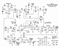 |
Circuit Theory of Operation
Here's a description of the Bass++ theory of operation in Thomas' own words:
I've been designing electronic bass drums for some two dozen years now, but the Bass++ is by far the best, if I may be so immodest. It uses no hard-to-find parts, is very stable and predictable and is a snap to build, weighing in at two chips only. And since it employs legitimate analog synthesizer technology and not the old ringing filter routine, it is very quiet. Before continuing, let me hasten to add that the Bass++ is great for bass drums (of course), but also is perfect for tom-toms, woodblocks and related instruments thanks to its wide range. Let's dig in and see how it works. Refer to the schematic.
A trigger is applied to jack J1. It is assumed that this follows the usual _Electronotes_ standard of being 0 to +5V in amplitude and 5 milliseconds wide. But if not, there is enough play in the "Sensitivity" control, R13, to accommodate most any signal. The output of IC2a will be a conditioned pulse, varying from 50 microseconds wide on up to 2.5 milliseconds, depending on the "Sensitivity" setting.
This signal is routed via D2 to the pulse stretcher composed of C8, R32 and Q2. With a greater duty cycle, LED D6 lights long enough to be readily seen and serves as a status indicator.
The VCO is made up of IC1a and associated components. This simple yet clever configuration comes straight from the LM13700 data sheet. C2 is the integrator timing cap. This can be changed to alter the audio range if desired. D4 and D5, along with R6 and R19 set the comparator trip points. The output is a triangle wave which is buffered internally by the circuitry connected to pins 7 and 8 of IC1a, with R9 biasing the buffer. Since this is a simple circuit, there is a slight pip at the extremes of the triangle, but this is hardly objectionable in a percussion circuit.
Strictly speaking, this is a current controlled oscillator. The current input is at pin 1 of IC1a. To make this simpler to use in a synthesizer setting, Q4 converts an input voltage to a current. The current will swing from 0 to 500 microamps, corresponding to an audio range of 10Hz to 5200Hz, perfect for drum work. And, oh, the 500 microamp max is on purpose---that's a good safe value to keep the OTA under so that it doesn't go into thermal runaway.
Since the internal buffers of the LM13700 introduce a negative offset, the output of the VCO is AC coupled by C14. The signal at this point is 10V peak-to-peak, so R24 and R2 drop this to 20mV peak-to-peak, which keeps the OTA operating in its linear region. R3 is provided to balance the differential input. Obviously, we're talking a VCA here, and the output current is converted to a voltage across R22. Observe C7. Its purpose is to smooth out the pip alluded to earlier. If you'd like a rougher edge to the sound, feel free to leave it out. The output of the VCA is then buffered by the internal circuitry at pins 10 and 9 of IC1b. Again, a capacitor (C15) blocks the negative bias, which also keeps the "Shell Volume" pot from sounding scratchy as you turn it; DC running through a pot is the equivalent of scraping your fingernails on a chalkboard. The signal finally winds its way to the mixer made up of IC2b.
Let's back up to the envelope generator (EG). The conditioned input trigger is fed to the EG by way of D1. C11 is the timing capacitor. A charge is rapidly dumped on to it for the attack, and then bleeds away through R4 and the "Decay" control R33. The envelope voltage is buffered by Q1. Notice that the entire voltage is developed across potentiometer R15. This voltage feeds R18 and is converted to a current by Q3. It is this current that controls the VCA mentioned above. As with the other half of the chip, the maximum value of the control current is kept at about 500 microamps. Say what you will about my designs, at least they don't catch fire...
But the wiper of the "Sweep" control taps off a variable amount of the total voltage, and this is converted to a current by R23 and Q4. The current controls the VCO frequency as previously described. The emitter of Q4 is sitting almost at ground (close enough for state work), and we take advantage of this to form a quick-and-dirty mixer. That is, the "Sweep" control provides the moving signal, while the "Pitch" control, R29, blends in a constant offset. And for external control, J2 can be used to pump in a keyboard voltage, say, to make the drum tunable by hand. Again, the three controls (sweep, pitch and external) are mixed by R23, R20 and R21 respectively since the emitter of Q4 is sitting at "almost ground." It's an inexpensive but more than adequate technique for a drum.
And talking about cost effective, how about that impact generator? I learned this clever technique first hand from Craig Anderton, the guy who gave me my break in electronic music design and writing. (He used it to simplify one of my designs for _Polyphony_ magazine). The conditioned input pulse is coupled via D3 to a tone control network made up of C9, C10, R7 and R11. The pulse can be kept sharp or smoothed out for a bassier response by means of R14, the "Impact Tone" control. This is then applied to R31 which serves as the "Impact Volume" control. Note that R31 is ten times greater in value than R14; this is to prevent loading. I suppose a purist might turn his nose up at this approach, but I rather like it. It probably doesn't have quite the range the active impact generator in the Mega Percussive Synthesizer does, but then again it only uses a fraction of the parts. I've recorded some good music with this method, and in my book that's all that counts.
The impact sound is mixed with the shell (R25 and R26, respectively) via op-amp IC2b. The output is AC coupled by C13, and attenuated by the "Master Volume" control, R16. Remember, this is a synth level signal at 10V peak-to-peak, so tame it a bit if you're going straight to a line level device. Alternatively, you could always drop R27 to 20K if you'd like to permanently set the Bass++ for line level work.
The Bass++ is indeed a simple circuit, but I hope you'll come to appreciate some of the touches that make it a slick design (if I do say so myself). Parodying Einstein, I've tried to make things as simple as possible, but no simpler. In particular, the use of the "almost ground" node for mixing the control voltages, the virtually skeletal impact tone generator, the most uncomplicated VCO imaginable, the use of a mere two garden variety chips, along with the usual parts-reduction schemes that have always motivated me, all add up to a unit that is reliable yet a snap to build. Thanks to the low cost and ease of construction, four of these could be easily built without breaking the bank to handle a bass drum, a low and high tom-tom and woodblock. And don't forget metronomes! The Bass++ would make an admirable sound generator for such a circuit.
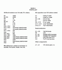
The Bass++ Parts List
Click the icon below to download the Bass++ parts list in PDF format.
 |
Finding Parts
The Bass++ parts are all very common and easy to find. Once good source for a one stop search for ICs would be Jameco.
![]()
Resources
Many of the concepts used in this and other drum voice designs are documented in Thomas' fine publication "Electronic Drum Cookbook", which is available through Magic Smoke.