
The VCF-1 Project
A Simple, Effective State Variable VCF
My, how time flies. Back in 2007 I put up the VCO-1 and VCA-1 pages. Both of these designs were examples of what I would consider to be Thomas' "legacy" designs. The VCO-1 design is a simple, yet highly musical VCO and the VCA-1 design is another uncomplicated, yet highly effective VCA that fits right in with the VCA-1. Back in those days, as Thomas' summer of fun ended and he headed back into the depths of another semester of academia, he fired another of these designs over the bow of my ship; the missing piece of the triumverate of legacy designs: VCF-1.
Before I had a chance to breadboard the design, I became involved in some other distraction (this was the period in which the Klee Sequencer PCB project was under full steam) and the VCF-1 never got tried out at all, much less published to this site.
But, of all the synth circuits I like tinkering with, it has to be the VCF. I never forgot about VCF-1, and this summer (now 2010) I mentioned to Thomas that I'd like to go ahead and try the circuit out and post it to the site. Thomas sent me an updated scan of the schematic and parts list.
The circuit, just like its VCO and VCA counterparts, is very straightforward and easy to build, and breadboarding it seemed to take no time at all. When I finally applied power to it, I immediately wished I had pursued it back in 2007 because I was immediately confronted with a very spunky, juicy little filter that seemed a perfect match for to the spirit of VCO-1 and VCA-1. Though it's ultimately a barebones state variable voltage controlled filter, it still, to me, has a wonderfully agressive personality. Perhaps it may be a clichéd term, but the words "old school" seem to spring into my brain every time I put this VCF into a patch.
The VCF-1 Filter
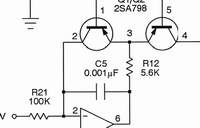
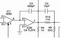
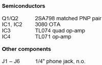
The VCF-1 design is a state variable voltage controlled filter that features low pass, band pass, and high pass outputs. The filter is controlled via a volts per octave signal input for keyboard tracking, a modulation input for envelope or LFO control, and, of course, it provides manual initial frequency control via a coarse tune control and a fine tune control. The design is based around the CA3080 OTA, though, just as with VCO-1 and VCA-1, with very little modification, an LM13700 could be used to replace both CA3080s.
This is what Thomas has to say about the design:
There's nothing particularly special about the VCF-1 filter; it's your basic, garden variety state variable filter which has appeared for years in data sheets and application notes for the 3080 OTA. More than anyone, the redoubtable Bernie Hutchins probably made this topology as popular as it is. Anyone wishing to understand how it works would be well-advised to peruse Bernie's comprehensive analysis in Electronotes, Volume 8, Number 71, pp.14-22. His variations are much more sophisticated, while my approach was to come up with the simplest VCF that sounded good enough to make real music with.
The exponential converter stage is also very standard, being the usual thing that Terry Mikulic, Dave Rossum and others popularized in Electronotes. The 2SA798 seems to be a good choice for the matched
pair nowadays, but truthfully for your run-of-the-mill filtering in a first synthesizer, the 2N3906 is probably just as adequate. I've never found dead-on tuning accuracy in a filter very important. The same thing goes for all those weird resonance controls---this one is simply a pot and that's the end of the matter.
It's not a bad filter, but there are better ways of handling things nowadays. However, the VCF-1 has the distinct advantage of being very simple to build and it uses fairly innocuous components. If the 3080 is hard for a person to find, then by all means he or she could just use an LM13700 without the Gilbert diodes connected---that's pretty much the same thing internally anyway. The biggest drawback of the circuit is that neither of these OTAs are as quiet as modern parts. But in lowpass mode it is doubtful one would detect any background noise anyway.
In the end, this design is really nothing more than a typical data sheet application with an equally old exponential stage slapped on. (My notebook indicates that I did the first draft of it in 1981 while at the University of Iowa Electronic Music Studios. I simplified the design somewhat in 1997, and returned to it finally in 2007 which is when you first saw it). There's nothing very clever about anything in it, but since you asked, you're welcome to it.
Well, I'm glad I asked. In practice, I've actually found this filter to be a lot quieter than other state variable filters I've tinkered with (but, then again, I found VCA-1 to actually be quieter than a number of VCAs I've played with over the years, and Thomas mentioned the same thing about VCA-1).
A Simple Circuit to Build

Here's a pic of my breadboarded VCF-1. You can see that it really doesn't take up a lot of breadboard space at all. I imagine a PCB or even protoboard would be even smaller.
I've always found state variable filters to be a bit more rambunctious than other types of filters; I think it's the nature of the beast. The resonance of this filter can be very agressive and get to be a handfull with this filter, but with judicious adjustment, it can also impart a smoother effect as well. I've found that the filter can be overdriven to impart a very "nasty" sound, while attenuation of the input signal will also produce a smoother sound that is not lacking at all in signal level. For me, these qualities enhance the versatility of this "simple" filter even more greatly.
The filter can indeed self oscillate at maximum resonance settings, but be careful to attenuate the signal going into modules downstream, as it can get really loud. At lower frequencies, with my setup, the oscillation would damp and fall away.
Aside from the really nice audio effects this filter has to offer, there is one other thing about it's operation I'd like to point out. As you view the schematics found further down on this page, you'll no doubt notice that a switch is provided at the input of the filter that allows either direct or AC coupling of the input of the filter. This switch is provided for instances where the full audio bandwidth of the signal is desired ; DC coupling allows very low notes to pass through uninhibited by the input coupling capacitor.
I must admit that I've spent more than a few hours just playing with this feature, because if you look further through the schematic, you can see that a DC signal can pass entirely through the filter without ever being "blocked" by AC coupling! In other words, when the input is DC coupled, the VCF-1 can be used to to process a control signal (as opposed to processing an audio signal). This opens up an entirely different can of worms!
Though a volts per octave signal cannot maintain its original accuracy passing through the filter, this ability of the filter should not be overlooked for producing some very interesting effects patches. I've found that, for example, patching a control signal (say, from a sequencer) to a VCO through the low pass section of this filter, while modulating the cutoff of the VCF-1 with an LFO can provide some pretty spacey effects. If the resonance is kept at minimum, it provides a variable slew effect, but when the resonance is turned up - look out! As the cutoff of the filter varies, the resonance of the filter provides a series of peaks to the signal that produces a unique FM type of effect on the VCO. The more resonance, the more intense the effect. If you build this filter, I urge you to experiment with this aspect of the filter.
Sound Sample
Of course the page would not be complete without some form of sample to give an idea of the character of the filter. Any filter can provide a seemingly infinite number of sounds and effects; it's hard to decide exactly what to supply for a sample. In this case I figured I'd put up a sort of mini-composition that used the filter to illustrate the character and usefulness of the filter.
Here's a multi-tracked composition that uses the VCF-1 as the sole filter in the composition. In addition to that, the X-4046 VCO is the only VCO used in the sample. All but one of the voices is made up of a patch of an output of the X-4046 VCO passing through the VCF-1 and then through a VCA. The one voice that does not use the X-4046 VCO is the noise output of my Blacet DSC 2000 (SN76477 Noise) filtered through the low pass output of the VCF-1 to produce the noise hit heard occasionally throughout the sample.
The background sequence is comprised of the pulse output of the X-4046 VCO modulated by a sine wave LFO and sequenced by the Klee Sequencer, through the low pass output of the VCF-1 and a then passed through a VCA. The cutoff frequency of the VCF-1 is modulated by a slow triangle wave and an envelope generator throughout this ostinato.
The drone backup of the composition consists of five tracks of X-4046 VCO through VCF-1: two low rampoid tracks through low pass, two higher octaves of LFO PWM modulated by a slow sine LFO through the bandpass output of the VCF-1, and another higher octave of sawtooth through low pass. The VCF-1 cutoff frequency is modulated by a slow triangle wave on each of these voices.
The first "solo" voice heard is sawtooth through the VCF-1 low pass, with the VCF-1 modulated by an EG.
The second brief solo voice is a triangle wave throught the VCF-1, low pass, with the VCF-1 modulated by an EG.
The trill-like glide up is two tracks of pulse output controlled by the TH keyboard which is, in turn, modulated by a square wave.
The thin, high voice is the synced triangle output of an X-4046 VCO which is using a second X-4046 as the master oscillator. The synced VCO is also modulated by the output of an EG. This signal passes through the high pass output of the VCF-1, which is controlled by a second envelope generator.
The last, short solo part is the synced pulse output of the X-4046 VCO through the low pass output of the VCF-1.
As the composition fades, you can hear the resonant sweep of the VCF-1 as various backing tracks are slowly modulated by a triangle LFO.
VCF-1 Schematics
Below are links to the schemata and parts list for the VCF-1
 |  |  |
| VCF-1 Sheet 1 | VCF-1 Sheet 2 | VCF-1 Parts List |
Circuit Notes
Looking through the schematic, you can see that, true to Thomas' other designs, there is a lot of bang for relatively few parts.
While there is only one audio input illustrated in the schematic, it's quite a simple matter to add more. Any additional audio inputs can be tied to the summing node at pin 2 of IC3a. Simply connect any addtional audio input to that point through a 100K resistor. Be sure to pass the signal through an attenuation control identical to the R32 Attenuate pot - you want to be able to not only balance multiple inputs, but attenuate them as well. Of course, one can include AC/DC switches, along with the 0.22uF coupling capacitor to each input, for maximum versatility.
As with the Audio Input, only one modulation input is shown on Sheet 1 (J2 Envelope). Additional control inputs can be tied to the summing node at pin 13 of IC3d. Each of these inputs can be summed to that point through 33K resistors.
As mentioned previously, the 2SA798 can be replaced by two 2N3906 or equivalent transistors.
For non-critical applications, the tempco resistor (R11) could be replaced with a metal film 2K resistor (in fact, that's what I used for breadboarding and the recording of the sound sample).
The Offset Trim pots R27 and R28 can be eliminated for simplicity's sake; I found that I was pretty much as happy with the performance of the filter before calibration of those trims as I was after. In the early days, there was quite a bit of variation of CA3080 offset, but in later versions of the IC, and this improved considerably. If you do choose to eliminate the trimpots, be sure to eliminate the 100K resistors (R25 and R26) but keep the 22 Ohm resistors (R2 and R4) in place.
As mentioned before, the CA3080s could be easily replaced using a single LM13700. If an LM13700 is used, be sure to leave the diode bias pins (pin 2 and pin 15 of the LM13700) unconnected.
Calibration
The volts per octave calibration is fairly straightforward:
Connect the low pass output up to something that can be monitored by ear (note: this signal can get very hot, so be very careful not to hook it up directly to an amplifier) .
Connect your voltage source (keyboard, MIDI to CV converter, etc) to 1V/Oct connector (J1).
Adjust the resonance and frequency control so that the filter goes into self oscillation. Adjust the V/Oct Trim (R6) for as close to a one octave interval per volt as possible.
If you've installed the offset trims (R27 and R28), first center the trimmers, and then adjust them for minimum DC deflection at the at low pass output as you adjust the coarse tune pot through its range. These trimpots are interactive, so you may have to go back and forth between the two a few times.
Finding Parts
The CA3080, Tempco Resistor, and 2SA798 may be the only moderately difficult parts to find. For more information on procuring these parts, you can refer to my VCO-1 Resource Page.