
Birth of The Klee Sequencer
Introduction
In August of 2006, as the summer began to wind down, I found my shop in one of its typically hopeless states of disorganization. Parts were strewn from one end of the shop to the other. I'd just finished up another summer of prototyping some Thomas Henry designs, and the MultiPhase project was lying fallow in a cardboard box awaiting reactivation. Breadboards with forgotten projects mounted to them were strewn about like so much collateral damage. I was having a hard time finding anything. I got it into my head to reorganize my shop and take inventory of what I had on hand, and to put these parts in places I was sure to be able to find them handily.
I piled my assorted parts into two general groups - analog parts and CMOS logic parts. In the preceding years I'd amassed somewhat of a large assortment of CMOS logic. Many of the parts were impulse buys and I really hadn't gotten round to using them. Generally, these parts came from purchases I'd made to "round out" an order or to bump an order up to the minimum price required to place the order. Sometimes I'd merely order a part because the description of the part's function caught my fancy. Such was the case when I'd ordered four CD4034 ICs from Hosfelt a couple of years earlier, then promptly forgot.
Forgot until this inventory, that is. As I sorted through the parts, I found these fat cockroach shaped ICs sitting quietly in their conductive bag, and I had to look up (again) the datasheet for the CD4034 to remind myself what exactly they were. Ah - there it is - they're 8-Stage tri-state bidirectional parallel/serial input/output bus registers. Of course, how could a DIY synth geek resist buying such a device based upon that description alone? 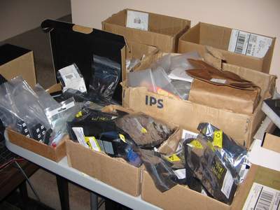
Taking inventory is not the most enjoyable task, so the mind wanders as parts are sorted, counted, and placed in their own little cubbyholes, and I found my mind wandering to what in the world could be done with 8-Stage tri-state bidirectional parallel/serial input/output bus registers. A few years earlier I had developed a fairly simplistic device that came to be called the "Klee Sequencer" based upon CD4006 shift registers, so I naturally thought of that application. The original Klee sequencer, though really fun to work with, was very difficult to program - it had no memory, and programming it was pretty much a random thing. This was fine unless one wanted to duplicate a sequence that one had happened across. At that point, to program the thing with a specific pattern was very close to impossible. The idea struck me that the CD4034 could provide a simple means for the device to remember what pattern had been programmed into it, and thus the germ of the idea for what I considered the "Model 2" Klee Sequencer was born.
The Model 1 Klee Sequencer
The name "Klee Sequencer" did not come along for some time after my first dalliance with shift register sequencing. The idea for that first experimentation, in turn, came from two sources: The quantized random voltage function from the Buchla 266 Source of Uncertainty module and Ken Stone's Gated Comparator.
Jeff Pontius and I had spent a happy period tinkering with Don Buchla's circuitry (we'd prototyped all of the circuits of the 266 SOU). I was particularly enamored over the mechanics of the Quantized Random Voltage function. The thought occurred to me that, instead of having fixed quantization steps for each output of of the 4006 shift register, it might be fun to actually make the voltages adjustable through pots. The Quantized Random Voltage function uses a pseudo-random sequence, which naturally would repeat after so many steps. In order to make the function more random and less pseudo-random, I turned to Ken Stone's gated comparator idea so that a signal input could be used to derive high or low bits in the shift register. I then enabled the register to loop a stored number of high and low bits ad nauseum through a simple switch setup that routed the output of the shift register back to the input.
 |
At the time I developed the circuit, I used the imaginative name "Shift Register Sequencer". On my original site, I posted the following on March 15, 2004:
I've been busy the past few weeks trying a few different things and working some stuff out on paper. My latest dalliance concerns the 4006 shift register.
The circuit uses a comparator to determine the input of the shift register by comparing a signal input (usually noise, but can be any input, really) with a reference signal level. This outputs either a 1 or a 0 to the shift register input. Since the input signal is not synchronized to the clock which is driving the shift register, the data bit that is loaded into the shift register at each clock pulse is more or less random.
I have the for D+4 outputs of the shift register buffered and going through pots to a mixer, with about a 10 to 1 weighting on each input. I then use the pots to set a different level for each bit that is coming out of the shift register. This produces a voltage pattern that can can consist of as many as 16 different 'notes' if each bit is set to a different voltage level going into the mixer. It's much like a random sequencer where the range of notes is set by the trim pots, and the pattern is set at random. Additionally, I can 'capture' a random pattern by inputting the end of the shift register back to the beginning.
The pattern can be influenced by the comparator reference level, a sort of 'probability control' - the lower the reference level, the more likely the comparator will be high when the clock pulse arrives when using noise as the input. I've found that using an LFO for the input can create interesting random patterns depending on the rate of the LFO versus the rate of the clock.
Any of the bit outputs can be used to gate an EG, which gives a whole new perspective on the generated pattern. If Bit 1+4 is clocking the EG, one 'snapshot' of the pattern is taken, a different view than say if bit 2+4 were gating the EG. What will be *really* interesting is to have two or more EG's firing different voices that are controlled by the mixed bit pattern - cool stereo effects are in the offing, I believe.
Finally, the two 'extra' bits, 2+5 and 4+5 add two more bits to play with, which would raise the theoretical number of steps to 64, and provide two additional gate options as well. I have found, though, that the more bits you try to mix, the complexity of mixing the bits to a CV pattern becomes exponentially more challenging.
Setting it up to perform a 'sequence' is very different than a step sequencer - it's like molding clay more than anything, because each pot not only affects the level of its bit, it also influences the mixed output level of the other bits when it's high at the same time. It can, however, be a very creative process.
Below is a sample that was composed using the 4006 shift register, other than the pad sounds and a bit of hand tweaking on filters and such, everything else was produced as a pattern by the 4006 shift register circuit. There's also a little cool noise that I got by clocking the 4006 at an audio rate with a random input. The sample is a bit over 5 MB, but I urge you to listen to it - it's amazing what a little old shift register can do.......
Sound Samples
I then posted my first ever "Shift Register Sequencer" (Klee Sequencer) composition, which was entitled "Shift Register Magnum Opus".
In this initial post was the inspiration of the name itself. Romeo Fahl built a version of this shift register sequencer and named it the "Klee Sequencer", using the word "Klee" as a play on words combining my reference to programming the thing being like "molding clay" with the similarity of its innate abstraction to the work of the artist Paul Klee (which is, of course, pronounced "clay").
On April 14, 2004, I posted the following composition created with the Shift Register Sequencer, with the following note:
Here is a sample of the Shift Register circuit I worked with last month - it's in the 'random' mode, and being fed with an LFO to determine the high or low state when a clock pulse arrives. More on that later.
After that, the circuit was more-or-less forgotten until August of 2006.
The Model 2 Klee Sequencer
On August 18, 2006, after the CD4034 epiphany of the inventory session, I began a thread at electro-music that would prove to be the incubator for what would ultimately become the advanced version of the "Shift Register Sequencer" - the "electro-music Klee Sequencer". You can see the thread by clicking on the electro-music logo below.
There were two main reason why the CD4034s appealed to me. The first reason was that the CD4034 allows the internal shift register to be programmed in parallel. In other words, each bit in the register can be independently set high or low, then that sequence of high/low bits can be shifted serially. The Model 1 Klee was based on the CD4006, which could only have data entered into it serially. With no battery protecting the data, as soon as one shut the device off, the pattern that was loaded randomly was dashed to the four winds.
The second reason was that the CD4034 has an output for each of its eight register positions. The CD4006 only provides data output at certain points in the shift register. This made things doubly hard to duplicate the internal bits, because there was no way to "see" these bits unless one slowly stepped through the bits and made a note of when each of the outputs was high or low.
But, if switches were arranged on the parallel inputs of a CD4034, then one could save any pattern by setting the switches high or low, and one could use the LED display to determine which bits were high or low at any given time.
It wasn't until a bit later that the fact dawned on me that the switches could be used to "program" the Klee instead of relying on random data input. This was a watershed moment in how I regarded the Klee Sequencer - random input programming from that point on was really just a small "feature" of the larger Klee functionality. Another vital element introduced by the bit-for-bit parallel outputs of the CD4034 was the ability to apply each of the outputs to its own pot. The original Shift Register Sequencer had only four pots tied to the outputs that processed the sixteen bit register as it cycled through.
The CD4006 has a much larger internal shift register than the CD4034; the CD4006 shift register can be up to 18 bits long (the Model 1 only used 16 bits of this register) but the CD4034 has only an eight bit shift register. This implied that two CD4034s would be reqiuired to duplicate the functionality of the original Shift Register Sequencer (Model 1 Klee).
Having the sixteen bit shift register split up into two eight bit "pieces" introduced new functionality - now each shift register could be made to circulate its own set of eight bits, or the two shift registers could be linked up to form the original sixteen bit shift register of the Model 1 Klee.
As the thread progressed, more ideas began to come as to how to implement the beast. A vital new feature of the Model 2 Klee sequencer was the range control.
With the original Shift Register Sequencer, the voltage applied to each of the four pots was a fixed voltage, and a rather large voltage at that. This large voltage made a small change in the setting of any of the four original pots to have a very large effect on the stepped voltage output. This contributed in a large part to the observation I'd made a fews years before to the effect that setting up a sequence with the Shift Register Sequencer was akin to molding loose clay.
Now that the Model 2 Klee had sixteen pots instead of four, this brought a new issue to the surface. With more pots contributing to the sequence, a large voltage had an even more drastic effect; with sixteen pots now available, things could become unmanageable in a hurry.
The solution was to provide a means to vary the voltage a pot would divide when a pot's bit was high. The idea was that if the voltage could be lowered, more pots could be used easily without forcing the stepped voltage repeatedly to the upper voltage rail. But, what should that range voltage be?
As it turns out, the question of what the voltage should be opened up a new area of functionality - the range control. While experimenting with different voltages, it was found that certain musical intervals of voltage (in a 1 Volt per Octave system) could produce different flavors of stepped sequences. Moreover, changing that range on the fly could transform some stepped voltages from one musical motif to another. This is not the same effect as combining a DC voltage with a step sequencer output wherein all of the musical intervals maintain the same relationship, only the base note is raised or lowered. The range control affected the musical intervals between the notes themselves.
As the electro-music thread progressed, more and more ideas came along. It was a wonderful exchange of ideas and discussion. In addition to discussion, people were actually simulating the device on their Nord Modular systems. I, too, found that generating interesting samples of the new system was almost as easy as falling off of a log. I'm not sure how many samples I produced in that period, but I figure it must have been in the zillions.
Somewhere within that thread, the Gate Bus system was born. Just as the Model 2 Klee was able to produce interesting voltage patterns seemingly at whim, it was also capable of generating control signals in the same manner. Eventually the Bus 1, Bus 3, and logical Gate Bus 2 systems came into being, fueled by Mickey Mouse Logic.
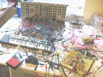
Things built to a crescendo. I finally came to realize there were so many features, it would take a panel the size of a refrigerator to implement the design. I finally settled on a set of features that closely resemble the electro-music Klee Sequencer of today. Andrew Sharp drew up a stripboard layout for the Klee. And, then, things just sort of.....stopped.
The thing about it was that the project had attained a level of complexity that would challenge any but the most experienced of builders. I myself had not moved it past the breadboard stage, and had only entertained the thought of actually building one. So, around February of 2007, the Klee thread pretty much ground to a halt.
The electro-music Klee Sequencer
In the spring of 2007, I received a message from Tom Fenn, one of the moderators of electro-music. He and Andrew Sharp had been discussing pursuing a PCB set for the Klee Sequencer, one that could be donated to electro-music, so that sales of the boards could be used to help defray the expense of running electro-music. This seemed like an excellent idea to me. In my opinion, without the input of the electro-music community, this project would have gone by the board like many of my other projects had done.
We set up a design team consisting, ultimately, of Andrew Sharp, Bill Manganaro, Tom Bugs, Tom Fenn and myself.
Andrew Sharp took on the task of designing the PCB. Andrew and I put our heads together and split the internal functions up between analog functions and digital functions, and designated that one board would be the Analog Board and the other board would be the Digital board. This enabled us to keep digital and analog functions adequately separated so as to reduce crosstalk. During this time there was a lot of necessary schematic clean-up to accomplish, which Andrew patiently put up with as the PCB needed to be changed nearly on a daily basis during this initial period to accomodate the corrections.
The Model 2 Klee sequencer design contained three options for setting the range voltage. One option used a rotary switch to choose between several different range values, one option used a constant current source and two range switches (one for setting octaves and one for setting half step values), and the third option allowed one to use a rotary pot to adjust the range value. Providing such diverse options did not translate well to the PCB, so we settled upon using the single rotary switch range value idea, with a rotary pot as an option to that (this did not require any drastic change in the PCB circuitry).
Bill Manganaro kicked in with putting in hysteresis on the signal input side and providing vital data for determining debounce characterstics of our prototype boards. Tom Bugs provided testing at 12V supplies, plus he was the only one of the team who had a banana jack interface. Andrew Sharp came up with the interconnect grouping concept and implemented the system on the PCBs. Initially Tom Fenn was to design a panel, but we went in a different direction.....
All prototyping members of the team reported protoype data that allowed the circuit to be fine tuned to the point that we were all comfortable with it.
The thread once again sparked to life, and I began producing more samples of the breadboarded Klee. Just as the Klee was "going to press" Jan Punter figured out through patching the Klee system on his Nord that inverting the signal as it looped from output to input actually provided some very useful extra functionality, and the Invert B function was literally tacked on before the design was declared "In the can".
This process had taken the entire summer of 2007. In the fall of 2007, we were still working on figuring out how many boards to order. In the meantime, in parallel to our project, Tim Heffman (one of the most capable Synth DIYers I have had the pleasure to have known) actually perfboarded a Model 2 Klee Sequencer!
Tim's remarkable build is the only Model 2 Klee in existence that I know of. He actually implemented the two rotary switch/constant current range function that we'd eliminated from the electro-music Klee Sequencer. Watching his Klee in action still makes me question that decision.
In the late fall/early winter of 2007, the Klee boards went on sale. I'd intially predicted perhaps thirty sets would sell. In fact, hundreds have sold and Klees are cropping up around the world.
Which leads me back to our never pursuing a panel design. At the time we were discussing it, I was the only person who'd ever operated the Klee, and that Klee was on a breadboard. Nobody quite knew what one would or should really look like, and few could really agree. Looking back on it, I'm glad we didn't lock it into a set design. One of the greatest pleasures of the experience is seeing the variety of implementations for the Klee. I chuckle to myself (ruefully, mind you) when I see discussions from knowledgable people of how the Klee was not designed for a "production environment". Hell no, it wasn't. It was never intended for the production environment. It was designed for a few hardcore guys out there to put together and play with. We (or at least I) never expected it to number in the hundreds. In fact, they're still on sale.
But, the variety! There are rack Klees, stand-alone Klees, Klees with rotary pots and Klees with sliders. There are horizontal Klees and rotary Klees (the remarkable panel available from Bridechamber, for example). There are Klees with multi-colored LEDs and LEDs on sliders. There are Klees of many colors.
Beautiful....
The Software Klee
Now, the greatest advancement in the Klee since its inception, Dan Nigrin's Defective Records has introduced the Software Klee. This application is, in my opinion, the logical next step in the Klee's evolution, and is extremely well executed. Now, any MIDI synthesizer can be Klee controlled. Again....beautiful......