Multiphase Technical details
Foreword
In the late winter/spring of 2006 I began work on the MultiPhase Project. In June of that year I diverted work to some other pressing projects, and, at this writing, have yet to return to the MultiPhase Project. In the time between the beginning of this project and now (late May of 2010) several projects have come between me and the completion of this project. In that time, I've begun work on the MultiPhase's sister project, the HEADLine project. I fully intend to follow through with this project. I think of all the projects I've documented on this site (and those I have not or have yet to document), I find the set of samples found on the MultiPhase Diary page to be some of the most compelling of those I've posted here. I plan to return to this project (and the HEADLine) after the summer season has ended. Following is the original documentation I wrote in 2006 concerning the technical aspects of the MultiPhase so far completed.
When I return the project, I will continue to refne the implementation. The concept is pretty much set in stone, but I've learned so much since those days in 2006. Working on the HEADLine has revealed finer technical details of how to accomplish the goals in mind.

Overview
The MultiPhase is designed to be a highly configurable rack mount opto-electric phase shifting device.
It contains two separate phase shifting sections (referred to as Phase Banks), with each bank modulated by its own control circuitry. The two phase banks can be operated individually, in parallel, or in cascade mode for up to 32 stages of phase shifting.
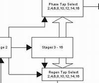
Each phase bank has two separate tap selection switches for tapping the wet signal (referred to on this page simple as the 'phase tap') and for regeneration. The tap selections for each phase bank are at the second, fourth, sixth, eighth, tenth, twelfth, fourteenth and sixteenth stage. Odd numbers of phase shift and regeneration are accomplished by injecting the input signal and/or the regeneration signal into either the first stage or the second stage.
This configuration allows anywhere from 1 to 16 stages of phase shift per channel for stereo operation, or anywhere from 1 to 32 stages of phase shift for mono operation..
Modulation sources include three LFOs and an envelope follower. Two of the LFOs, based on Ray Wilson's "Cool New LFO" design, provide triangle, pulse, and sine waveforms each. Each LFO is adjustable between triangle and saw, sine and rampoid sine, and variable pulse width (the LFO's, except for the sine shaping, are taken directly from Ray Wilson's LFO design). A third LFO, based on Thomas Henry's Quadrature Function Generator, provides two different waveforms - Triangle and Hypertriangluar. This LFO is capable of offsetting the selected waveform, sent to Phase Bank B by 0, 90 or 180 degrees in relation to the waveform supplied to Phase Bank A.
The envelope follower is based on René Schmitz's treatment of the Elektor envelope follower.
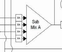
The modulation scheme is planned so that each phase bank can be operated from either an inverted or noninverted copy of each source so that anti-phase modulation is possible between the two sections for any waveform. Moreover, a submixer is included in the modulation path of Phase Bank A so that the level of LFO1, LFO2, External CV and the Envelope follower controlling the two phase banks can be adjusted simultaneously, in phase or antiphase, by a single set of controls. A master intitial phase control is also provided so that the initial phase of the two phase banks can be adjusted simultaneously.
Each phase shift section will have a continuously variable mix of wet to dry signal. Voltage controlled crossfaders (voltage control normalled to the selected LFO2 output) are planned so that the Phase Bank A and Phase Bank B wet signals can be crossfaded from channel to channel.
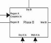
The MultiPhase project pays particular attention to the importance of regeneration in the creation of dramatic phase shifting effects. Each section contains a soft-knee limiter/compressor as well as a high-cut control. Each section's regeneration can be either inverted or non-inverted, and, as mentioned before, an even or odd number of stages can be selected separately for regeneration. Cross regeneration (the ability to send the regeneration tap from one section to the opposite section and vice versa) is implemented as well.
Multiphase Front Panel
This panel is currently around the fourth revision. Certain things are still a bit fluid in the design of the MultiPhase, and some minor aspects of the panel are bound to change a bit.
In any event, it's a 3U high rack panel. I believe I have used the proper spacing in order to fit the front panel components on the board. Much as I dislike the idea, I plan to put all of the LFO outputs on the rear panel - there's just no room at the inn on the front panel. A patch bay can bring them round to the front if having them back there is too much of a pain.
MultiPhase Block Diagrams
Above are the links to the basic block diagrams of the audio and CV paths in the MultiPhase. As soon as I reach the point in the project where they become available, I'll post actual board interconnections.
Phase Board A and Phase Board B
Phase Bank A and Phase Bank B operate from two electrically identical 'Phase Boards' - Phase Board A and Phase Board B. Each phase board contains the 16 all pass circuits associated with its respective phase bank. The actual current sink control transistors will be on these boards as well, though at this writing I do not have them installed - I want to play with that section a bit more, and will match the transistors for beta and Vbe to see if that makes much of a difference. The current sinks themselves will be fed from the Control Voltage Mixer Board, which is as yet undeveloped.
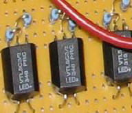
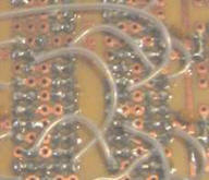
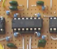
I used my favorite protoboard from Futurlec for these (same stuff I used on the Dim C main boards). It's great for keeping things organized, and provides a perfect opportunity to keep a good star power and grounding scheme going.
The picture of Phase Board A has the Even/Odd switch connected to it. This is a C&K 7211 ON ON ON configured as follows:
Down Position - Signal input and resonance insertion is at Stage 1.
Middle Position - Signal input is at Stage 1, resonance insertion is at Stage 2.
Up Position - Signal input and resonance insertion are both at stage 2.
The yellow wires along the top of the board are the tap points - right now I'm just clipping onto them with alligator clips.
Schematic of Phase Board A
I have not posted one for Phase Board B, but it is identical in every way to Phase Board A, just the reference designators have been changed to accomodate it.
One may notice the difference in the number of capacitors on the schematic and the number actually used on the boards. This is a result of my 'matching' capacitance with the Vactrols. I'm not sure if this is all that effective, but I went through the excercise anyway.
Basically, I measured each Vactrol at minimum resistance (IE, maximum positive CV offset). I then used a measured value close to what all of the Vactrols measured and used that as my reference. I then calculated the value all of the other Vacrols actually deviated from that one value and converted them to a percentage of how far off they were. I then matched the capacitors to that same percentage, but in the opposite direction.
Say a Vactrol varied from the reference value by a positive 10%. I would then match capacitors to 2n7 minus 10% of 2n7 to match that Vactrol value. I did this by measuring 10% tolerance capacitors of 1n, 1n2, 1n8, 2n2, and 2n7 values and mixing and matching one or two in parallel to add them together to get the values that I needed.
To be honest, selecting Vactrols that match closely at that minimum resistance value and just using 2n7 capacitors is most likely just as effective. In any event, I know the Vactrols and caps all agree at two points - minimum resistance and maximum resistance of the Vactrols. What happens in between is the magic of the MultiPhase. I *figured* that would gag you =-D.
Another difference that may be noted between the schematic and the board pics is that capacitors 135 through 149 are not present on the board pics. I took the board pictures before I put in these caps.
When I breadboarded the phase banks, I would have problems with high frequency oscillation when chaining greater than sixteen stages. To assuage this, I put in low value (47 pF) feedback caps to kill the oscillations. I chalked this up to all of the flying wires of the breadboard, but kept it in mind when laying out the Phase A and Phase B boards - I went through special pains to leave these pads open should I actually need the capacitors on the finished boards.
I'm glad I did. Each board individually worked fine, but when chaining them - hoo boy - let's just say I built a very exotic combination white noise generator/radio receiver. From stage to stage (above 16 stages) the noise got progressively worse, with stage 32 ending up as a roaring font of noise and Mexican radio. I put in the 47pF caps, and really got jiggy with the last two stages, using 100 pF caps. This killed the problem completely. My concern was having all of those caps in there would dull the high end, but I've noticed no difference in that regard.
I have the current sink on the schematic, though without any values. As mentioned above, I'm still experimenting with that.
(Mis)Using the Thomas Henry Sine Shaper
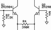
Thomas Henry's books are an endless source of wonderful designs, understandable theory and inspirational ideas. One of the bits I've culled from his works is an outstanding sine shaping circuit that ***does not use an OTA***, taken from the Thomas Henry Book "Making Music with the 566" (Copyright 2003, Midwest Analog Products).
Especially with the demise of the CA3080, and even before that, I was loathe to use an OTA for sine shaping after discovering this gem of a circuit. Instead of an OTA, Thomas resorts to the discrete differential pair method of deriving a sine wave from a triangle waveform. It is an exquisite circuit that can yield distortion figures under 1%. Thomas does a bit of magic with the circuit that I'll reserve for Thomas' words himself - IOW, buy the book, which is available through Magic Smoke Electronics:
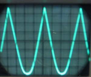
I use this circuit for all of my sine shaping. In the case of the MultiPhase, I'm using Ray Wilson LFO's, which put out the requisite 10Vp-p triangle wave, centered around 0V (ground). In fact, I am using the circuit for the normal sine outputs of Ray's LFO, eschewing Ray's use of the LM13700. However, I am also using Thomas' circuit for forming the hypertriangular waveform. Previous to this, I was using a rather fussy method of FET distortion to get the hypertriangle wave. René Schmitz mentioned the idea of mis-adjusting a sine shaper to get the same effect. Bingo! I put Thomas' circuit to work and below is a rather blurry picture of the result:
When misadjusted for hypertriangularity, the output is roughly 10Vp-p, with a very slight negative offset - close enough for the girls I go out with, or, in this case, the MultiPhase. I may or may not balance it out a bit downstream - right now it works perfectly well, and sounds great modulating the MultiPhase.
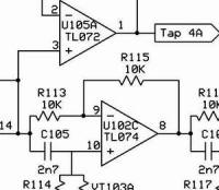
Thomas Henry was kind enough to give me his permission to post this circuit fragment. Below is a schematic of the the essence of Thomas' circuit itself. I've left out a portion dealing with bumping up the 566 output to 10Vp-p, and I've left off the 1K output resistor because this portion of the circuit will be going to the CV mixer of the MultiPhase. I've used a TL072, and I have one half of it sitting at rest, waiting to be used for something - I usually have no problem finding work for an unused op amp section.
LFO3 - Wave Select and Phase B Offset
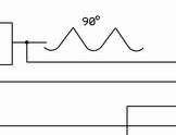
The concept of LFO3 has changed a bit. Previously the idea was to be able to select either a single triangle wave sent to both phase bank CV mixers, a single hypertriangle wave sent to both phase bank mixers, or a hypertriangle wave sent to Phase Bank A and a 180 degree offset hypertriangle wave sent to Phase Bank B.
That idea has now changed - instead of a third Ray Wilson LFO, LFO3 will now be the Quadrature Function Generator designed by Thomas Henry, published both in Polyphony magazine and his book "Build a Better Music Synthesizer". The speed range control will be dropped in favor of a Wave Select switch. The function of this two position switch is to determine whether LFO3 will send triangle or hypertriangular waves to the phase banks. The three position Offset switch will select which offset of the wave selected by the LFO3 Wave Select Switch to send to Phase Bank B. The down position will be the 0 degree wave (same as sent to Phase Bank A), the middle position will send the 90 degree offset quadrature wave to Phase Bank B, and the up position will send the 180 degree offset wave to Phase Bank B.
Anyone who's read any of Thomas Henry's book will recognize his theorem of "Never open a can of beans with a stick of dynamite." Rarely do I manage to meet that criteria - not that it's not very good advice, it is, it's just that usually I'm not clever enough to operate the can opener.
When the idea struck me, I sat down to sketch out a switching scheme. The first design I came up was classic "stick of dynamite".
The Stick of Dynamite method uses three waveshapers to convert the 0, 90 and 180 degree triangle waves to hypertriangular waves. Each of the triangle outputs and hypertriangular outputs are connected to a three pole, double pole ON-ON switch. The 3PDT switch feeds a double pole double throw ON-ON-ON switch, which sends the wave selected by the first switch to Phase Bank B.
The Stick of Dynamite aspect of the design is this: it requires three wave shapers, and a 3PDT switch, which is rather large and possibly too bulky to fit into my current panel design.
Dissatisfied with this method, I went back to my scratch pad and designed the Can Opener method.
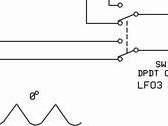
To my brain, this method is more complex, but yet accomplishes the same task with only two waveshapers and a DPDT ON-ON switch instead of the 3PDT switch.
The first section of the Wave Select Switch selects between the 0 degree triangle wave and 0 degree hypertriangular wave.
The second section of the Wave Select Switch selects between the either the 90 degree or 180 degree triangle wave OR the 90 degree or 180 degree hypertriangular wave. Whether it's the 90 degree version or 180 degree version of the selected wave is determined by one section of the LFO3 Offset switch.
The first section of the LFO3 Offset switch selects between either the 0 degree triangle or hypertriangular wave, as selected by the the first section of the Wave Select Switch, OR the wave selected by the second section of the Wave Select Switch, described above.
The second section of the LFO3 Offset Switch directs either the 90 degree or the 180 degree triangle wave to the second waveshaper. This in effect chooses either 90 degree or 180 degree offset for the triangle or hypertriangular wave, depending on which wave is selected by the second section of the first switch. Whew!
The method of switching at this point is academic - I may just go with a switching IC and the switches themselves will just control the on/off stages of the IC switch sections, but the same general design will be followed.
Wet Signal Crossfaders
The wet signal crossfaders come in handy for a couple of things - mixing in a portion of the opposite phase bank's wet signal to the wet signal of the current phase bank makes for some great variation in timbre/sweep, and modulating the cross-faders with a single CV adds greatly to the pallette of stereo panning sweeps (even without modulating the crossfaders, the stereo field can be affeted by the crossfaders as well).
In review, a phase bank's wet signal, before it is mixed with the original dry signal feeding the phase bank, can be mixed with the wet signal from the opposite phase bank in any ratio, as set by the XFade controls. The crossfaders can be modulated so that a constantly varying amount of crossfading can be accomplished. The control input to the phase banks is normalled to the selected wave of LFO2, the level of which is controlled by the XFade CV Level control. An external CV can control the crossfade panning as well by inserting the CV into the crossfade CV input - this disconnects LFO2 and allows the control voltage to control the crossfading.
In the case of voltage controlled crossfading, either by external CV or internal LFO2, the XFade controls act as the starting point of the crossfade. Setting them in center feeds an equal amount of each phase bank's wet signal through the crossfader. The expected CV input is a 10Vp-p signal centered around 0V. With the XFade control centered, -5V will allow full signal from the associated phase bank to pass, with no signal from the opposite phase bank. +5V will allow the opposite phase bank's signal to fully pass, with the associated phase bank's signal fully attenuated.
I've changed things a bit since I drew the panel diagram and defined the crossfade function. Originally, I had a bipolar level control for each crossfader. I figured out that this was fairly redundant - the idea was, one could modulate the crossfader's opposite of what LFO2 or the external CV was doing, in varying amounts. Well, that can be accomplished by the inverting attenuators in the modulation control section. And, I found that the need to modulate the crossfaders in different amounts was rare to non-existent.
So, I dropped the extra pot and added an 'XFade Invert' switch. This switch will allow inversion of the wet signal from the opposite phase bank before it's applied to the crossfader. Now *that* I found is very useful - it opens up another pallete of timbral and panning effects.
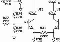
I used Mark Verbos' crossfader (adapted from a Buchla design) as a starting point for the MultiPhase crossfader. It's Vactrol based and is quite effective.
I never had much luck with the original circuit as drawn - the Vactrols drop very low in resistance, and they are the input resistors to an op amp that has a 100K feedback resistor. IIRC, the Vactrols drop to around 4.7K, or thereabouts, so that gives the circuit a gain of around 21. IE, the circuit would shriek and distort.
I dropped the 100k feedback resistor to 10k, and added 2k2 resistors in series with the Vactrol LDR's. This cut the gain down considerably, and when I re-invert the signal in the second stage, I get a little of that back with a 100k input/82k feedback resistor. The signals exactly match in level from input to output, and, as with the original circuit, there is no amplitude 'bump' in the middle of the crossfade - it works quite well.
The other task was balancing out the XFade and CV control inputs to render a smooth crossfade. A range of 0 to 6.5V will give a smooth crossfade from one side to the other. I set the center trim to between 3.25 and 4 volts. I then created a +5V and a -5V source for the XFade controls to operate between. I scale that voltage down in the first stage of the control section with 33k input and 22k feedback resistors. I allow the external CV to have a slight bit more effect by using a 30K input resistor (to account for possible variations in control voltage sources). Instead of a bipolar attenuator, I use a simple unipolar attenuator (read pot set up as a voltage divider) to allow the user to easily cut out all possible modulation by simply setting it to full CCW. The second stage inverts the control signals back to original polarity after going through the first stage.
The LEDs (D1 and D2) are panel mount - the brighter they glow, the more of the opposite wet signal is being crossmixed into the associated phase bank's wet signal.
The XFade Invert switch just selects between the direct wet signal, or an inverted copy of it before it is fed to the crossfader op amp.
This circuit, BTW, will work great for crossfading any signals in a modular synth. Obviously the XFade Invert Switch and op amps wouldn't be necessary in that case.

